


 +86 18130251359
 teflowpumps@tlpumps.com


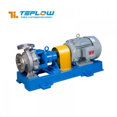
In centrifugal pump operation, the coupling is the core component connecting the motor and pump shaft. Its alignment directly impacts equipment efficiency, lifespan, and safety. Misalignment can easily cause vibration, noise, bearing wear, and, in severe cases, shaft fracture and seal failure. Therefore, it is crucial to master standardized correction methods.
一、Preparation before calibration
1.Tool preparation: You need to prepare a dial indicator and stand, ruler, feeler gauge, wrench, spirit level, and various specifications of iron plugs (0.1mm-2mm). At the same time, prepare equipment installation drawings to clearly define the allowable range of radial and end face deviations.
2.Equipment inspection: Turn off the power to ensure the machine is shut down, clean the oil and impurities on the coupling, check whether the bolts are loose, whether the elastic elements (such as elastic pads) are intact, and replace any damaged ones in time. Use a spirit level to check the horizontality of the pump body and the motor base. If there is a significant tilt, first use the anchor bolts to initially level it.
3.Safety protection: Workers must wear labor protection equipment, and warning signs must be set up around the equipment; when working at height or in narrow spaces, a stable platform must be built, and anti-fall and anti-suffocation measures must be taken.
二、Common calibration methods and operating steps
The common methods for coupling calibration are the ruler and plug gauge method (applicable to small centrifugal pumps with low precision requirements) and the dial indicator method (applicable to large equipment with medium and high precision requirements).
Ruler and plug gauge method:
1.Preliminary positioning: Place a ruler close to the outer circle of the coupling, observe at 0°, 90°, 180°, and 270°, determine whether there is radial clearance and record it.
2.Plug gauge measurement: Insert a plug gauge at the gap to determine the radial deviation value; then insert the plug gauge into the coupling end face and measure the end face clearance at four positions to determine whether there is angular deviation.
3.Adjust deviation: If radial deviation is large, loosen the motor's anchor bolts and adjust the horizontal position by adding or removing base iron plugs. If end face deviation is large, adjust the motor's height. Repeat measurements until the deviation is within the allowable range (usually ≤0.1mm radially and ≤0.05mm end face, refer to the equipment manual).
Dial indicator method:
1.Install the dial indicator: Fix the dial indicator stand on the pump side coupling, make the dial indicator measuring head contact the outer circle (measure radial runout) and end face (measure end face runout) of the motor side coupling respectively, adjust the pre-compression amount (0.3-0.5mm) and adjust to zero.
2.Rotation measurement: Slowly rotate the coupling clockwise and record the radial (R0, R90, R180, R270) and end face (S0, S90, S180, S270) runout values every 90° to ensure smooth rotation.
3.Calculate the deviation: radial deviation ΔR = (R0 + R180)/2 - (R90 + R270)/2; end surface deviation ΔS = (S0 + S180)/2 - (S90 + S270)/2. If it is non-zero, the corresponding deviation exists.
4.Adjust the deviation: When ΔR is positive, add iron sheets to the motor feet away from the pump side or reduce them on the side close to the pump; when ΔS is positive, add iron sheets to the motor feet to adjust the height, and negative values are adjusted in the opposite direction. Measure multiple times until the radial runout is ≤0.05mm and the end face runout is ≤0.03mm.
三、Post-calibration inspection and trial run
1.Comprehensive inspection: Review the deviation data to confirm that it meets the requirements; check the tightness of the coupling bolts and the installation status of the elastic elements.
2.Trial run: Run at no load for at least 30 minutes, observe the vibration and noise, touch the bearing seat (≤70℃) and motor housing (≤80℃); if there is no abnormality, run with load, monitor the vibration speed (≤4.5mm/s), current, and temperature. If there is any abnormality, stop the machine and recheck.
四、Precautions
1.Environmental control: Operate when the temperature is stable. If the temperature fluctuates greatly, shading and heat insulation are required to prevent thermal expansion and contraction from affecting the accuracy.
2.Multiple measurements: Because the coupling may become stuck or vibrate, multiple measurements are required to obtain an average value to ensure data accuracy.
3.Proceed step by step: Slowly adjust the anchor bolts, and do not stack more than 3 iron sheets to prevent the equipment from tilting and components from being damaged.
4.Regular review: Check the coupling alignment every 3-6 months, correct deviations in a timely manner, and extend the life of the equipment.
In short, coupling calibration must follow standard procedures and select the right method to ensure accuracy, so as to reduce equipment failures and ensure stable industrial production.


 +86+0563-5093318
